
On a heat-traced line, thermal insulation is not ordinary pipe insulation — it is part of the heating system itself. The cable produces heat; the insulation decides where that heat stays. If the insulation is too thin, compressed, wet or badly installed, the cable has to compensate for every watt lost: power demand rises, cold spots appear, and in the depths of winter a line freezes exactly when it is supposed to be protected.
Heat tracing insulation is the layered thermal barrier applied to pipes, valves, flanges, tanks and equipment that carry electric trace heating or steam tracing. It keeps the fluid inside its design temperature band, reduces the power drawn by the heating cable, prevents freeze-ups and keeps surfaces safe to touch. This guide covers insulation selection, thickness calculation, installation over live cables, the relevant standards, the mistakes that destroy efficiency and a practical buying checklist.
It is based on field experience in industrial insulation projects and on the requirements of IEC 62395, IEEE 515, ISO 12241, ASTM C680 and ASTM C1695, so it can be used as a reference for both design and procurement.
At a glance:
- In a heat-traced system, insulation sets the cable’s power demand: poor insulation means higher wattage and a bigger electricity bill.
- Thickness should come from a heat-loss calculation (ISO 12241 / ASTM C680), never from habit or guesswork.
- The heating cable must never be compressed or laid under sharp metal fasteners.
- A proper vapour barrier and a sealed jacket are the difference between a 5-year and a 20-year system.
- Use removable insulation jackets on valves, flanges and any point that is opened for maintenance.
- Surface temperatures above 60 °C are a burn risk and an HSE obligation that thickness can solve.
Contents
- What is heat tracing insulation?
- Why insulation is critical on heat-traced lines
- How the tracing system retains heat
- Insulation types for heat tracing
- Layer build-up of a heat tracing insulation system
- Thickness selection and calculation
- Installing insulation over a heating cable, step by step
- Valves, flanges, supports and electrical entries
- Removable jackets vs traditional insulation
- Seven mistakes that destroy tracing efficiency
- Standards and technical references
- Energy savings and payback
- Applications by industry
- Safety, HSE and surface temperature
- Buying checklist and RFQ
- Cost drivers
- FAQ
- Conclusion
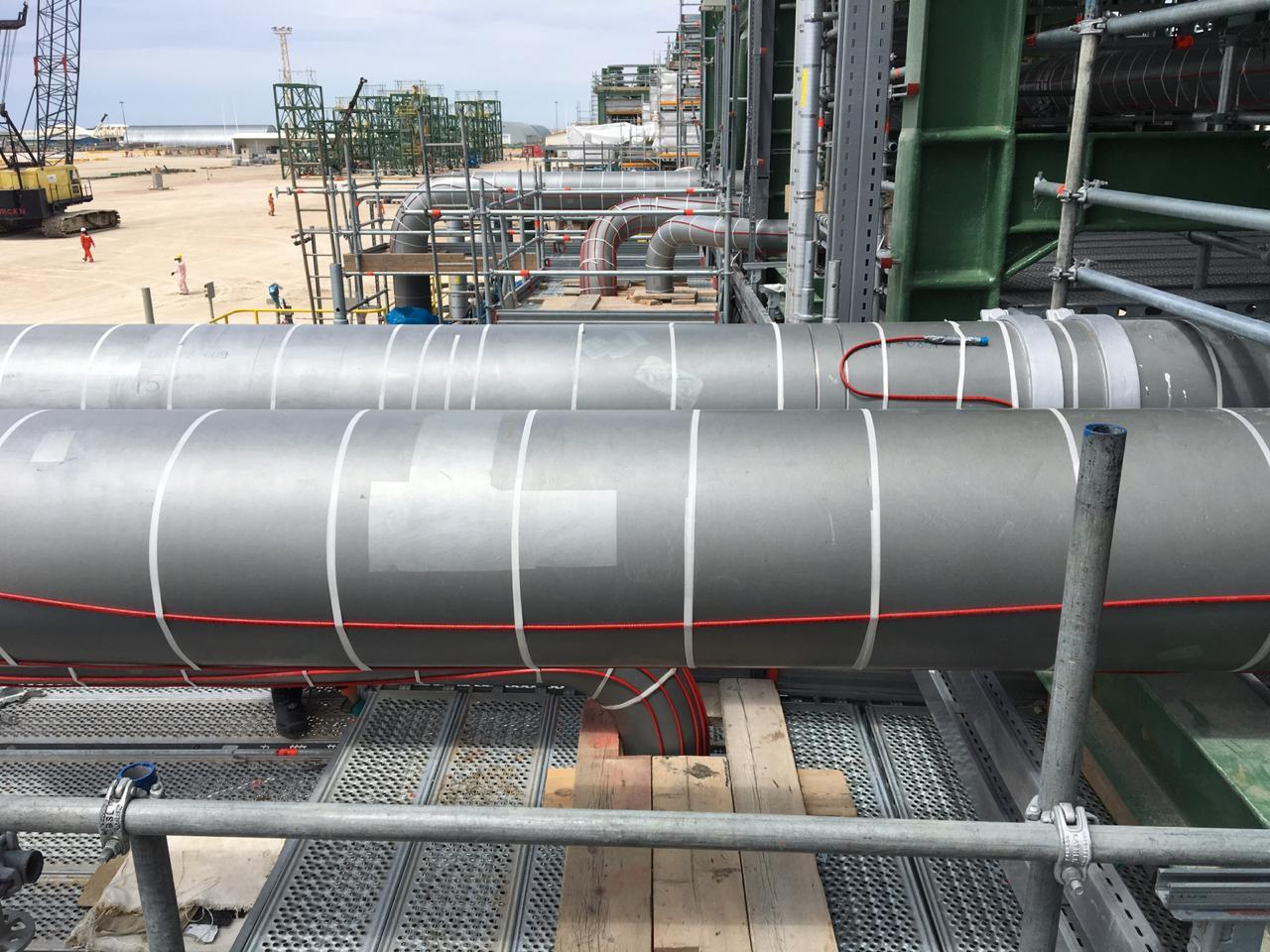
What is heat tracing insulation?
Heat tracing insulation is the thermal barrier applied over equipment that carries trace heating, in order to achieve three goals at once: hold the fluid at its design temperature, reduce the power consumed by the heating cable, and keep the outer surface safe. “Heat tracing” refers to the heat source itself — an electric cable or a steam line — while “heat tracing insulation” is the cover that keeps that heat inside the system.
When a cable maintains a pipe at a given temperature, its output must equal the heat lost through the surface plus the heat needed for warm-up. Every improvement in insulation therefore acts directly on electricity consumption and on the thermal capacity of the system. In real projects, the right insulation is often the difference between a stable line and one with cold spots and repeated shutdowns.
The difference from ordinary pipe insulation lies in the installation requirements: ordinary insulation only has to slow heat loss, whereas heat tracing insulation must coexist with a live cable, sensors, junction boxes and periodic inspection.
| Criterion | Ordinary pipe insulation | Heat tracing insulation |
|---|---|---|
| Primary goal | Reduce heat loss | Hold fluid temperature + cut cable power + surface safety |
| Interaction with cable | None | No compression or abrasion; cable route and spacing must be preserved |
| Surface temperature | Usually designed below 60 °C | Must satisfy cable temperature and personnel safety together |
| Access and inspection | Low | High; sensors, thermostats and terminations must stay accessible |
| Sealing | Important | Critical; water ingress destroys efficiency and drives CUI |
| Geometry | Mostly straight pipe | Valves, flanges, pumps, tanks and complex shapes |
Why insulation is critical on heat-traced lines
1. Cable power demand and electricity cost
Self-regulating cable increases its output as heat loss rises. In practice, inadequate insulation forces the cable to run at — or beyond — its design point, which means higher energy consumption, a hotter cable and a shorter service life. Correct insulation lowers the design wattage and gives the cable headroom to operate safely.
2. Freeze protection and production continuity
On water, fire-water and aqueous process lines, a freeze-up means a split pipe, a jammed valve and a stopped line. Insulation is the only layer between the fluid and the ambient cold; if it is interrupted at a support, a flange or a pipe end, that point becomes the starting point of the freeze.
3. Personnel safety and surface temperature
Hot surfaces are a burn hazard. Safety references such as ASTM C1055 and ISO 13732-1 use roughly 60 °C as the basis for brief contact with a metal surface. Insulation thickness and quality determine the surface temperature directly — see the safety section below.
4. Temperature stability and product quality
In food, pharmaceutical and chemical plants, temperature swings mean quality loss, viscosity changes and fouling. Insulation reduces those swings, stabilises the process and lowers the control load.
5. Corrosion under insulation (CUI)
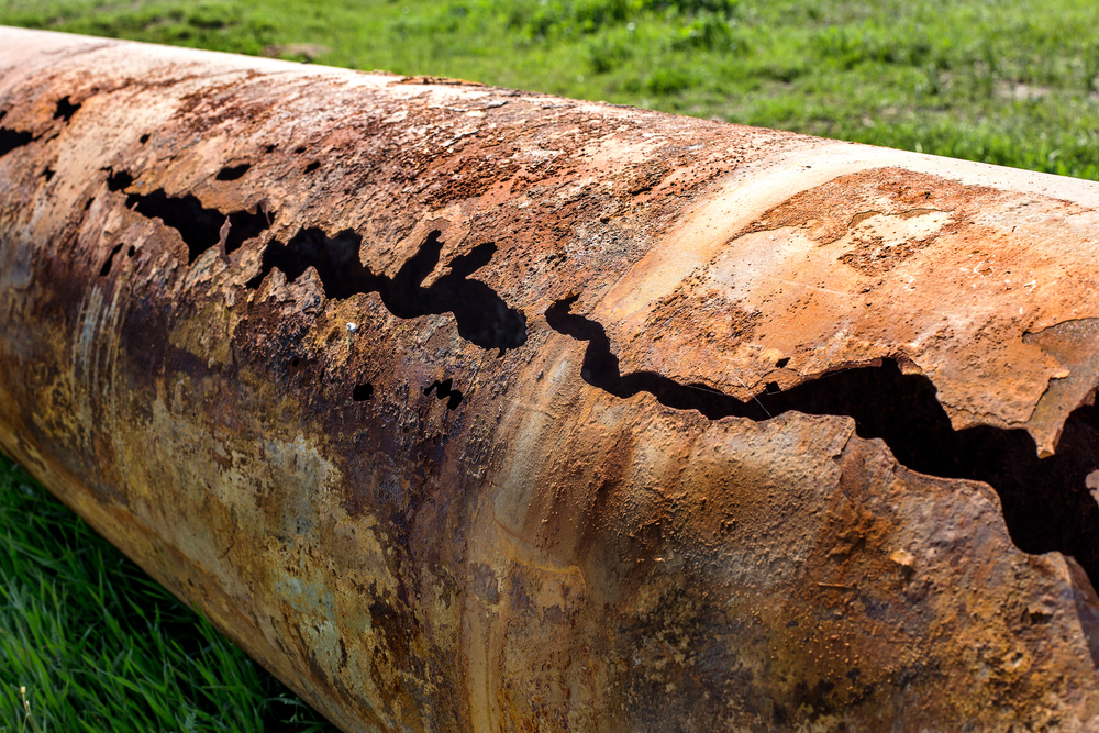
Badly installed insulation traps water and accelerates corrosion under insulation, especially in the temperature range where moisture repeatedly evaporates and condenses. The vapour barrier, a sealed jacket and correct detailing are the three main controls, described in the layer section.
How the tracing system retains heat
Before choosing insulation, identify the heating system, because it sets the operating temperature, the heat distribution and the installation constraints:
| System type | Characteristics | Typical operating range | Typical use |
|---|---|---|---|
| Self-regulating cable | Output adjusts with temperature; can be cut and overlapped | Up to roughly 65–150 °C depending on model | Temperature maintenance, freeze protection, water and process lines |
| Constant wattage cable | Fixed output along the length; design-sensitive | Up to roughly 150–200 °C | Defined lengths and higher temperatures |
| MI (mineral insulated) cable | High resistance to heat and aggressive environments | Up to roughly 400–600 °C | Steam lines, refineries, hazardous areas |
| Steam tracing | Heat from a steam line; needs trapping and control | Depends on steam pressure | Heavy, continuous process lines |
The principle is the same in every case: insulation lowers the heat load so the source can hold the design temperature at minimum output. Insulation that is too thin keeps the source running continuously; insulation that is too thick without calculation only adds cost and weight.
Insulation types for heat tracing
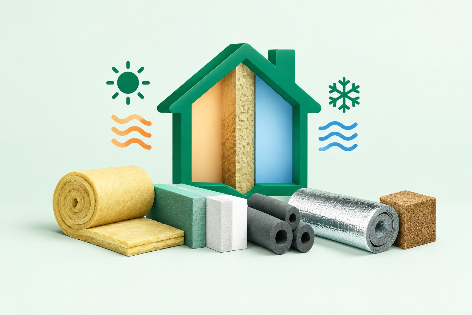
Material selection follows the operating temperature, the environment, the equipment geometry and the inspection requirement. A brief comparison of the common options:
| Insulation material | Thermal conductivity (W/m·K) | Service temperature | Advantage / limitation |
|---|---|---|---|
| Removable insulation jacket | 0.035–0.050 | Depends on the core | Fast to fit and remove, ideal for valves and flanges / higher initial cost |
| Preformed rock wool | 0.038–0.045 | Up to about 650 °C | Economical, good thermal resistance / moisture sensitive |
| Aerogel | 0.015–0.021 | Up to about 650 °C | Thin profile, high efficiency / premium price |
| Elastomeric (closed cell) | 0.033–0.040 | About -120 to 120 °C | Moisture resistant, easy to install / limited high-temperature range |
| Cellular glass | 0.040–0.055 | Up to about 400 °C | Virtually impermeable to moisture / heavy and brittle |
| PIR | 0.022–0.026 | Up to about 150 °C | High efficiency at low temperature / more limited fire performance |
These values are indicative references that depend on temperature and density; final design must use the manufacturer’s catalogue data for the actual project conditions.
1. Removable jackets — the first choice for valves and flanges
On heat-traced lines, the most frequently opened points lose the most heat and carry the most risk. A jacket with an insulated pillow and a coated fabric outer shell can be opened in minutes, allows sensor inspection and is re-fitted without damage, so maintenance no longer destroys the insulation. This is the logical choice for valves, flanges, filters and any fitting operators need to reach.
2. Preformed rock wool and glass wool
For long pipe runs at medium to high temperature, preformed mineral insulation is the most economical option with acceptable performance — provided a proper metal or composite jacket and careful sealing are installed. In wet environments, performance degrades quickly without a vapour barrier.
3. Aerogel — thin profile, high efficiency
Where space is restricted, geometry is complex, or a retrofit cannot afford a larger insulation diameter, aerogel delivers the same performance in less thickness thanks to its very low conductivity. Cost is its main limitation.
4. Elastomeric and cellular glass — for low temperatures
On refrigeration, HVAC and chilled-water lines, closed-cell insulation with high moisture resistance is used. In these duties, preventing condensation and surface icing matters as much as reducing heat gain.
Layer build-up of a heat tracing insulation system
A professional heat tracing insulation system has several layers, each with a defined job. The cross-section below shows them on a pipe fitted with a heating cable:
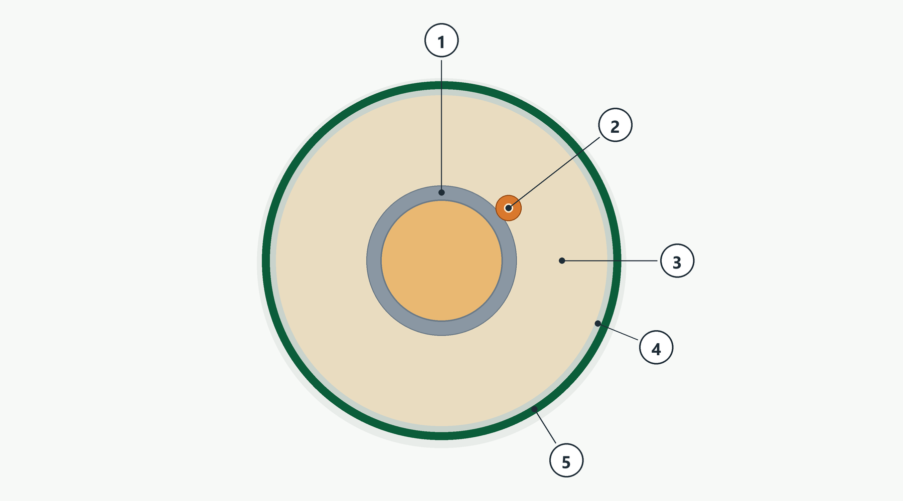
- Pipe wall and hot fluid: the primary heat source. The surface must be clean, dry and free of rust so the layers bond and perform.
- Heating cable: fixed at controlled spacing, without pressure, sharp bends or contact with cutting metal edges.
- Thermal insulation: thickness from the heat-loss calculation; material matched to service temperature and environment.
- Vapour barrier: the moisture barrier. In humid or cold climates, omitting it means efficiency loss and corrosion under insulation.
- Protective jacket: mechanical strength, weather sealing and a professional finish; material (stainless steel, aluminium, coated fabric) follows the environment.
Where the cable leaves the insulation — at a junction box or a thermostat — the cable route must be protected with a guard and sealed. These small details are where water enters and where failures begin.
Thickness selection and calculation
Thickness is the most important design variable, not because “thicker is better”, but because it balances allowable heat loss, cable output and cost. The main inputs are:
- Fluid maintain temperature and cable design temperature
- Minimum ambient temperature and wind speed at the installation
- Pipe diameter, material, wall thickness and run length
- Insulation type and conductivity at the mean temperature
- Cable type and output, voltage and maximum circuit length
- Maximum surface temperature for personnel safety
The reference method is ISO 12241 (calculation rules for thermal insulation of equipment) together with ASTM C680. The output is heat loss per unit length (W/m), and from it the required cable output and the optimum insulation thickness. The chart below shows the general relationship for a typical line:
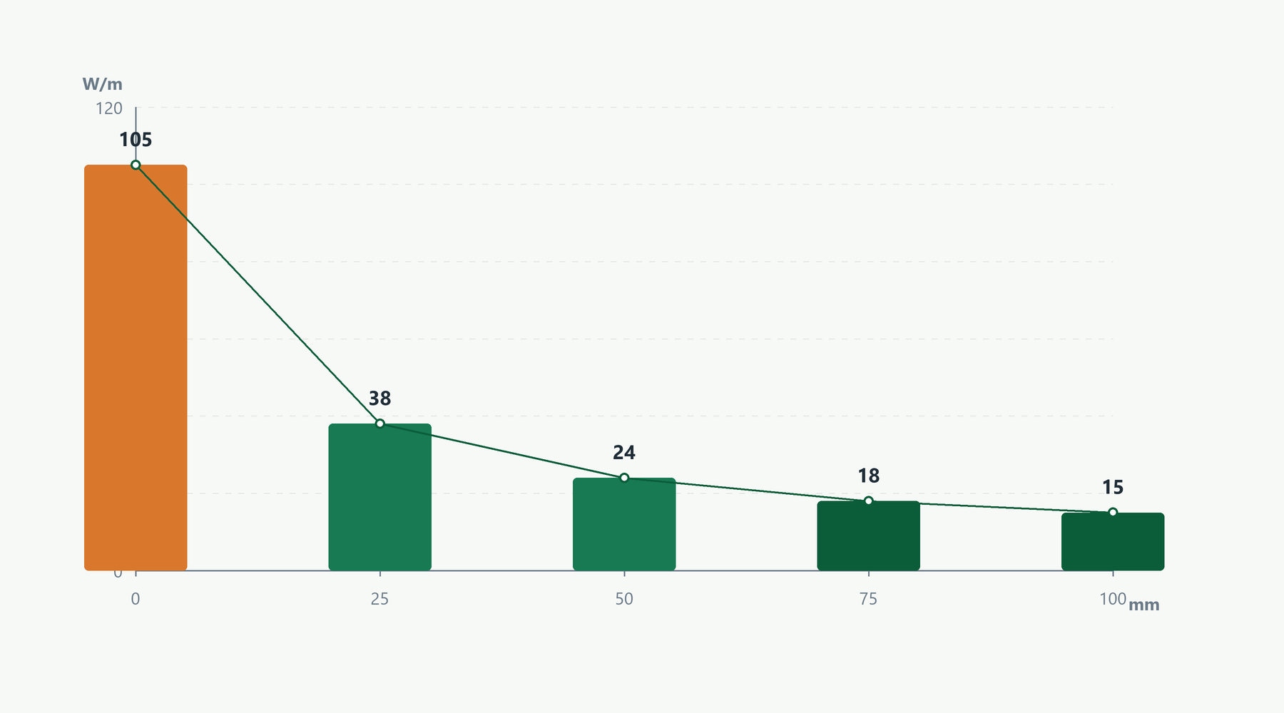
Design note: thickness beyond the optimum only increases capital cost and structural weight, because most of the loss reduction has already been captured. The table below is a preliminary guide for early sizing and does not replace a project calculation:
| Pipe size | Temperature maintenance (up to 100 °C) | Temperature maintenance (100–200 °C) | Freeze protection (5 °C maintain) |
|---|---|---|---|
| Up to 2 in (DN50) | 30–40 mm | 40–50 mm | 20–30 mm |
| 3–6 in (DN80–DN150) | 40–50 mm | 50–65 mm | 25–40 mm |
| 8–12 in (DN200–DN300) | 50–65 mm | 65–80 mm | 30–50 mm |
| Above 12 in | 65 mm and above | 80 mm and above | 40 mm and above |
Outdoors and in windy locations, thickness and sealing should be more conservative: wind raises the surface heat-transfer coefficient and increases losses.
Installing insulation over a heating cable, step by step
Workmanship matters as much as material selection. Expensive insulation badly installed performs worse than average insulation installed correctly. The standard sequence:
- Inspect the surface and the cable: the pipe must be dry and clean; the cable must be undamaged, free of abrasion and without sharp bends.
- Test the cable before insulation: record insulation resistance and circuit continuity; access is far harder once covered.
- Secure the cable and sensor: fix the cable at regular intervals with the approved tape; place the sensor at a representative point, shielded from direct cable influence.
- Fit insulation without compressing the cable: insulation sits over the cable, never on top of it under pressure; maintain cable clearance at penetrations.
- Install the vapour barrier: with adequate overlap and the correct adhesive; laps must face down so they shed water.
- Install the protective jacket: overlapped, with non-creeping fasteners and full sealing; sharp edges must be covered.
- Insulate valves, flanges and supports: with removable jackets or preformed pieces, without cutting the main line insulation.
- Seal every penetration: all laps, the cable entry and the sensor connection must be watertight.
- Label: mark the cable route, junction box and insulated zone so future maintenance does not damage them.
- Test and hand over documentation: post-insulation circuit and insulation-resistance tests, surface temperature readings and an installation report.
Field warning: on self-regulating systems, local pressure and sharp bends shorten cable life and create hot spots; and covering the thermostat or a junction box with insulation disrupts control. These two mistakes appear more often than any other in inspections.
Valves, flanges, supports and electrical entries
Most heat loss and most insulation failures happen at the details, not on straight pipe:
- Valves and flanges: their surface area equals several metres of pipe; use removable jackets so inspection and repair do not destroy insulation.
- Supports and hangers: thermal bridges and water paths; insulation and vapour-barrier details must be shown on the drawing.
- Bends and tees: need preformed pieces or layered work without compression, with sufficient overlap.
- Pumps and tanks: complex geometry and vibration; the insulation must accommodate equipment movement.
- Cable entries and junction boxes: mechanical guard and sealing; flexible conduits must not be under tension.
- Sensors and thermostats: accessible and uncovered; their location must be marked on the insulation drawing.
Removable jackets vs traditional insulation
| Criterion | Removable jacket | Traditional (fixed) insulation |
|---|---|---|
| Installation time | Fast, no specialist skills | Long, requires specialist labour |
| Access for repair | Open and close in minutes | Requires demolition and rebuild |
| Reusability | Yes, many cycles | No, essentially single use |
| Initial cost | Higher | Lower |
| Life-cycle cost | Lower on frequently opened items | Higher on frequently opened items |
| CUI control | Better, thanks to periodic inspection | Weaker |
| Complex geometry | Yes, custom built | Limited |
Practical conclusion: fixed insulation is economical on straight pipe that is never opened; on valves, flanges, filters and any point opened several times a year, a removable jacket wins clearly on maintenance cost.
Seven mistakes that destroy tracing efficiency
- Guessing the thickness: without a heat-loss calculation the cable either overworks or fails to hold the design temperature.
- Compressing insulation onto the cable: creates hot spots, abrasion and premature cable failure.
- Skipping the vapour barrier: moisture stays inside the insulation and conductivity rises sharply.
- Leaving valves and flanges bare: these items are a large share of total line losses.
- Poor jacket sealing: water entering at top laps and pipe ends is the most common cause of performance loss.
- Covering sensors and thermostats: control is disrupted and the real temperature is never read.
- No documentation or labelling: later maintenance damages the cable and the insulation route, and the system quietly fails.
Standards and technical references
Referencing the standards both protects design quality and provides the acceptance basis for industrial projects:
| Standard | Subject | Relevance here |
|---|---|---|
| IEC 62395-1 / -2 | Electrical resistance trace heating systems for industrial and commercial applications | Design, installation and test requirements |
| IEEE 515 | Testing, design, installation and maintenance of resistance trace heating | Acceptance basis for cable and system performance |
| ISO 12241 | Calculation rules for thermal insulation of equipment | Heat-loss and thickness calculation |
| ASTM C680 | Heat gain/loss and surface temperatures of insulated systems | Loss estimation and savings |
| ASTM C1695 | Removable and reusable thermal insulation covers | Requirements for valve and flange jackets |
| ASTM C1055 | Surface conditions that produce contact burn injuries | Surface temperature safety limits |
| ISO 13732-1 | Human contact with hot surfaces | About 60 °C for brief contact |
Energy savings and payback
The effect is easy to quantify. If poor insulation raises average cable output from 18 W/m to 45 W/m, then over a 100 m line:
- Extra demand: (45 − 18) × 100 = 2,700 W, i.e. 2.7 kW
- Extra energy over 8,000 operating hours per year: 2.7 × 8,000 = 21,600 kWh
- Annual extra cost: extra energy × your industrial electricity tariff
For a precise figure, calculate heat loss with ISO 12241 in both cases — existing insulation and proposed insulation — and multiply the power difference by operating hours and tariff. In many projects, corrective insulation pays back in under two years, especially once downtime and repair costs are included. For a project-specific estimate, see heat tracing insulation by Klevers Aryana or contact our technical team.
Applications by industry
- Oil, gas and petrochemical: controlled-temperature process lines, sulphur and high-pour-point products
- Power generation: steam, feedwater and sampling lines
- Water and wastewater: exposed water mains, pump stations and fire-protection lines
- Food and pharmaceutical: product temperature holding, prevention of crystallisation and fouling
- Buildings and utilities: external cold and hot water pipes, roofs and car parks
- Cold climates: freeze protection for tanks and transmission lines
Safety, HSE and surface temperature
In heat-traced systems insulation does two safety jobs: it lowers the surface temperature to prevent burns, and it prevents direct contact with the cable and electrical terminations. The chart shows how increasing thickness brings the surface below the 60 °C threshold:
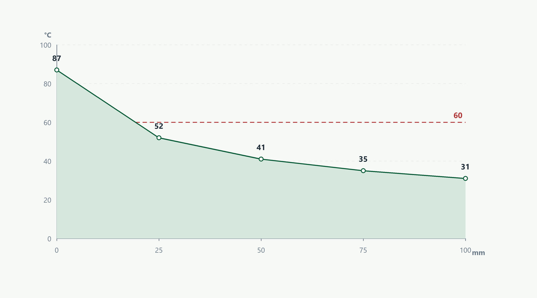
- 60 °C on metal surfaces is the common basis for brief-contact safety design.
- In explosive atmospheres, cable selection and insulation work must meet the area (Ex) requirements.
- Fit “hot surface” and “trace heating” warning labels on the jacket.
- Before opening a jacket for maintenance, isolate and lock out (LOTO) the cable circuit.
Buying checklist and RFQ
To receive an accurate, comparable quotation, include the following in your enquiry:
- Pipe diameter, material and total run length
- Maintain temperature and cable design temperature
- Minimum ambient temperature and installation conditions (outdoor, basement, wet area)
- Tracing system type (self-regulating, constant wattage, MI, steam)
- Number and type of valves, flanges, filters and access points
- Proposed insulation thickness and material
- Jacket type (coated fabric, stainless steel, aluminium)
- Project safety requirements and standards
- Whether installation or technical supervision is required
- Delivery deadline and shipping conditions
Cost drivers
There is no single price for heat tracing insulation, because it combines material, thickness, geometry and jacket. The main drivers:
- Insulation material: rock wool is the most economical option and aerogel the most expensive.
- Thickness: more thickness means more material volume and weight.
- Geometry: valves and flanges need custom patterns and more fabrication.
- Jacket type: stainless steel and technical coated fabrics cost more.
- Quantity and item variety: large projects benefit from scale.
- Installation and supervision: correct workmanship is part of life-cycle cost.
Send your line data for current pricing and a project quotation, and our engineers will recommend the optimum option.
Why Klevers Aryana
- Free technical consultation on insulation type, thickness and jacket for your conditions
- Project supply in a wide range of thicknesses and lengths, including custom valve and flange pieces
- Support before and after purchase, including inspection and handover
- Track record in oil, gas, petrochemical, power and building projects
- Delivery across Iran and supply of complementary insulation accessories
Frequently asked questions
How is heat tracing insulation different from ordinary pipe insulation?
The heat-transfer principle is the same, but heat tracing insulation must coexist with a live cable and sensors, must not compress the cable and must control surface temperature.
What is the minimum insulation thickness for a heat-traced line?
There is no fixed number. Thickness comes from a heat-loss calculation to ISO 12241 using maintain temperature, pipe size and ambient conditions. The table in this guide is only preliminary.
Is thicker insulation always better?
No. Past an optimum point, extra thickness produces little additional saving while raising cost, weight and installation complexity.
When should removable jackets be used?
On valves, flanges, filters and any item inspected or serviced periodically; removable jackets prevent insulation from being destroyed at every intervention.
Is a vapour barrier really necessary?
In humid, cold and outdoor conditions, yes. Moisture ingress can multiply the conductivity of the insulation and accelerates corrosion under insulation.
Is it safe to insulate over a heating cable?
Yes, provided the cable is undamaged, terminations are sealed and the circuit has been tested. Testing before and after insulation is part of the standard procedure.
What surface temperature is safe for personnel?
About 60 °C is used as the basis for brief contact with metal surfaces; longer contact or special conditions require stricter limits.
How long does heat tracing insulation last?
With the right material, a suitable jacket and careful sealing, it lasts many years; workmanship and maintenance determine service life as much as the material itself.
Conclusion
Heat tracing insulation is part of the heating system, not a decorative cover. A calculated thickness, installation that never compresses the cable, a sealed vapour barrier and a suitable jacket together determine electricity consumption, temperature stability and personnel safety. If you operate a heat-traced line, check the insulation before upgrading the cable or adding power — in many cases correcting the insulation is cheaper and faster than expanding the heating system.
Read more
- Heat Tracing Insulation — product page and technical data
- Thermal Jacket Insulation — pillow-type and cladding jackets
- What Is Thermal Insulation? — complete guide to types and selection
- Industrial Valve Insulation — selection and installation for valves
- Ceramic Refractory Blanket — structure and high-temperature use
- Passive Fire Protection (PFP) — fire protection for oil and gas facilities
References
- IEC 62395-1:2013 — Electrical resistance trace heating systems for industrial and commercial applications
- IEEE 515 — Standard for Testing, Design, Installation, and Maintenance of Electrical Resistance Trace Heating
- ISO 12241 — Thermal insulation for equipment — Calculation rules (iso.org)
- ASTM C680 — Estimate of heat gain or loss and surface temperatures of insulated systems (astm.org)
- ASTM C1695 — Removable and reusable thermal insulation covers
- ASTM C1055 — Heated system surface conditions that produce contact burn injuries
- ISO 13732-1 — Ergonomics of the thermal environment: contact with surfaces
Klevers Aryana, with more than two decades of experience, supplies specialised thermal insulation, refractory materials and industrial sealing systems in Iran. Our sales engineering team advises on the right insulation for heat-traced lines, thickness selection and custom valve and flange pieces.
📞 Free consultation and quotations:
Phone: 02191305505
Website: klevers-aryana.com
Email: info@klevers-aryana.com